

Introduction: 3D Printed Arduino Powered Quadruped Robot


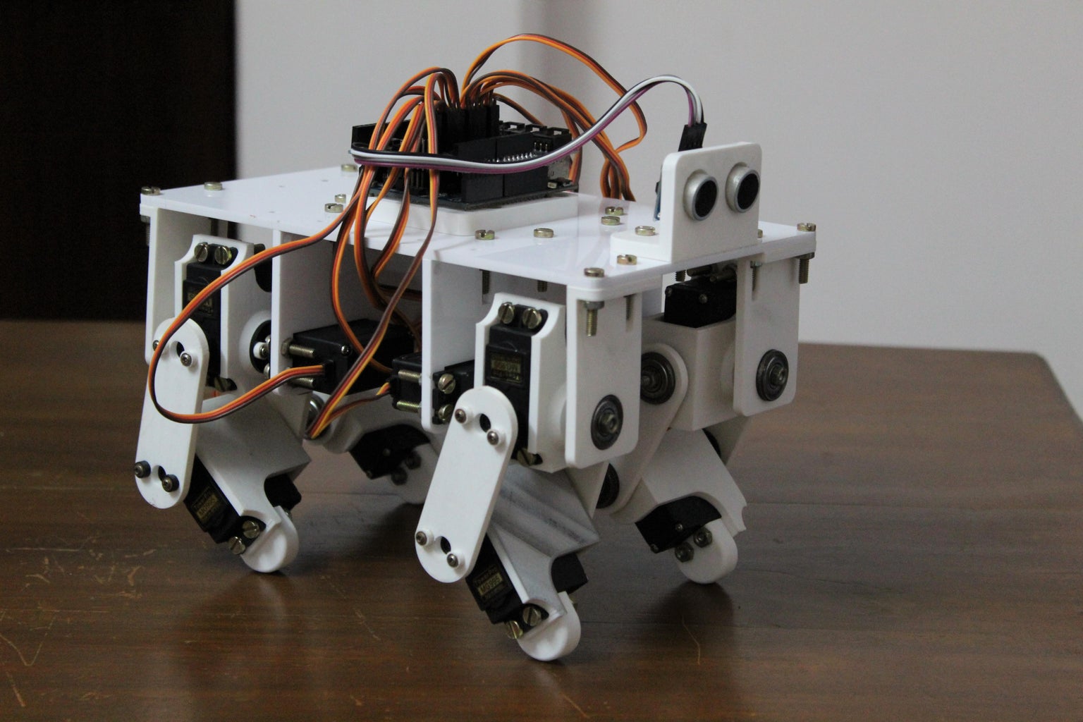
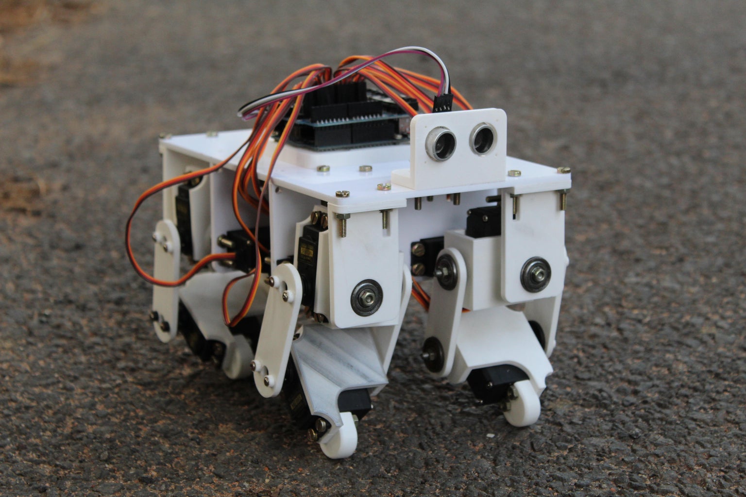


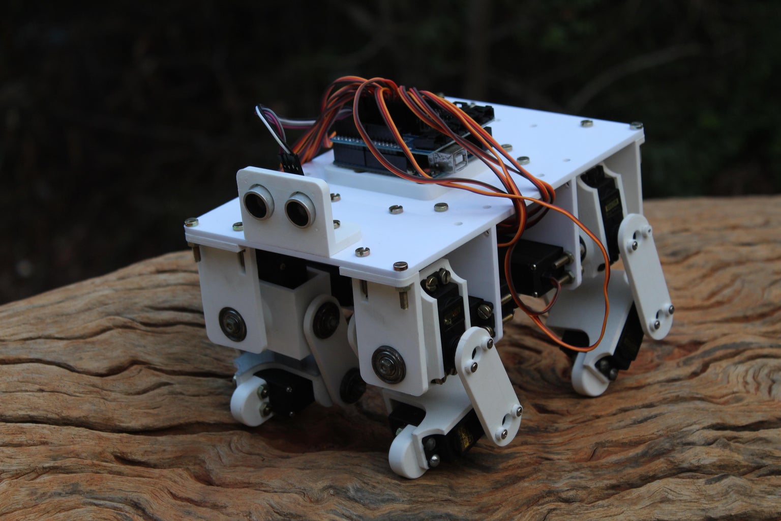
From the previous Instructables, you can probably see that I have a deep interest for robotic projects. After the previous Instructable where I built a robotic biped, I decided to try and make a quadruped robot that could imitate animals such as dogs and cats. In this Instructable, I will show you the design and assembly of the robotic quadruped.
The primary goal while building this project was to make the system as robust as possible such that while experimenting with various walking and running gaits I wouldn't have to constantly worry about the hardware failing. This allowed me to push the hardware to its limit and experiment with complex gaits and motions. A secondary goal was to make the quadruped relatively low-cost using readily available hobby parts and 3D printing which allowed for rapid prototyping. These two goals combined provide a robust foundation to perform various experiments, letting one develop the quadruped for more specific requirements such as navigation, obstacle avoidance and dynamic locomotion.
Do check out the video attached above to see a quick demo of the project. Follow on to create your own Arduino Powered Quadruped Robot and do drop a vote in the "Make it Move Contest" if you liked the project.
Step 1: Overview and Design Process
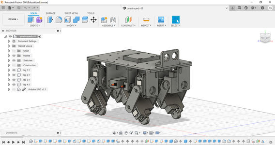


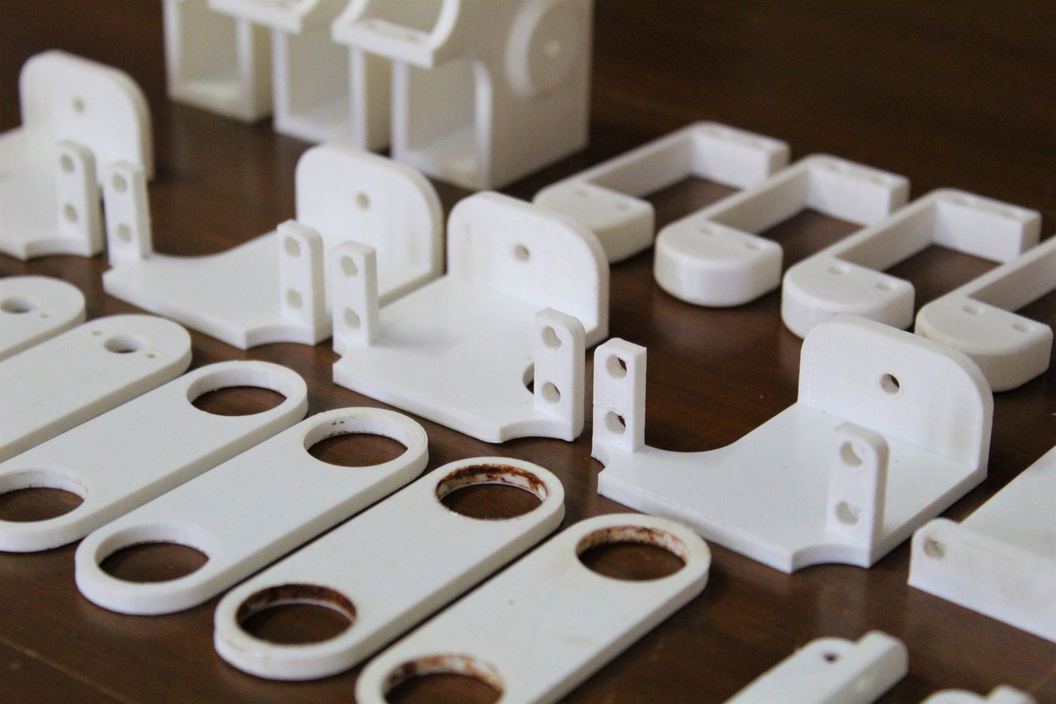
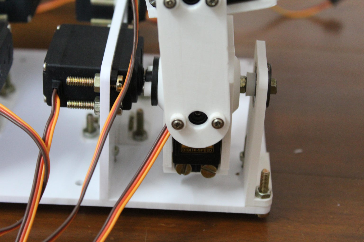
The quadruped was designed in Autodesk's free to use Fusion 360 3d modelling software. I began by importing the servo motors into the design and built the legs and body around them. I designed brackets for the servo motor which provides a second pivot point diametrically opposite to the servo motor's shaft. Having dual shafts on either end of the motor gives structural stability to the design and eliminates any skewing that may occur when the legs are made to take some load. The links were designed to hold a bearing while the brackets used a bolt for the shaft. Once the links were mounted to the shafts using a nut, the bearing would provide a smooth and robust pivot point on the opposite side of the servo motor shaft.
Another goal while designing the quadruped was to keep the model as compact as possible to make maximum use of the torque provided by the servo motors. The dimensions of the links were made to achieve a large range of motion while minimizing the overall length. Making them too short would make the brackets collide, reducing the range of motion, and making it too long would exert unnecessary torque on the actuators. Finally, I designed the body of the robot onto which the Arduino and other electronic components would mount. I have also left additional mounting points on the top panel to make the project scalable for further improvements. Once could add sensors such as distance sensors, cameras or other actuated mechanisms such as robotic grippers.
Note: The parts are included in one of the following steps.
Step 2: Materials Needed

Here is the list of all the components and parts required to make your very own Arduino Powered Quadruped Robot. All parts should be commonly available and easy to find in local hardware shops or online.
ELECTRONICS:
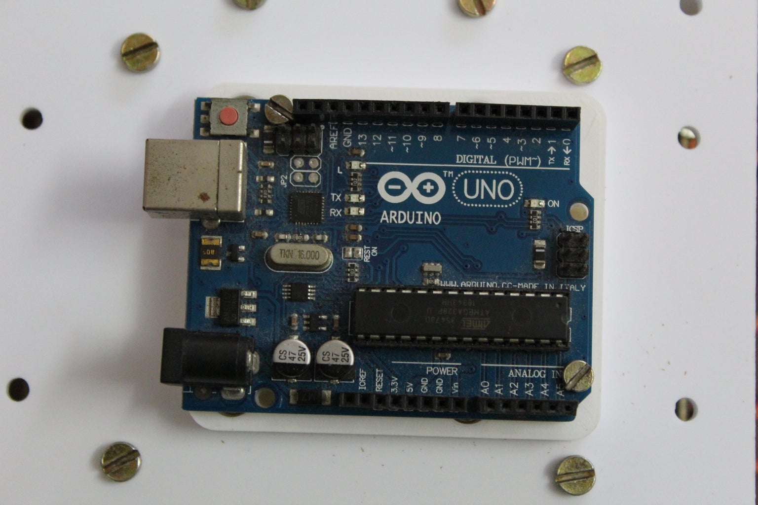
Arduino Uno x 1
Towerpro MG995 servo motor x 12
Arduino Sensor Shield (I recommend the V5 version but I had the V4 version)
Jumper Wires (10 pieces)
MPU6050 IMU (optional)
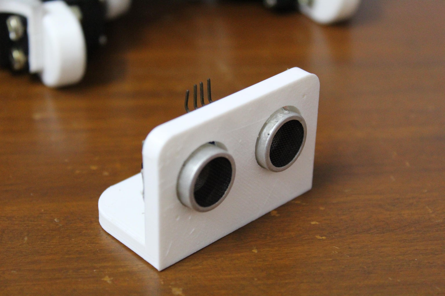
Ultrasonic Sensor (optional)
HARDWARE:
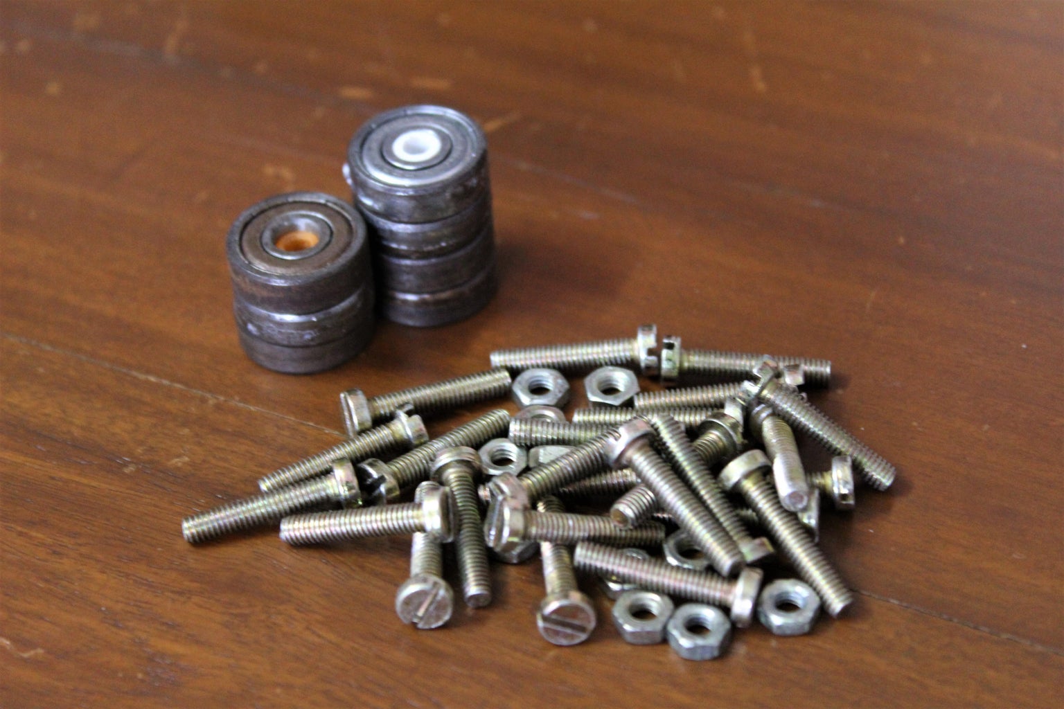
Ball Bearings (8x19x7mm, 12 pieces)
M4 nuts and bolts
3D printer filament (in case you don't own a 3D printer, there should be a 3D printer in a local workspace or the prints can be done online for quite cheap)
Acrylic Sheets (4mm)
TOOLS
3D printer
Laser cutter
The most significant cost of this project is the 12 servo motors. I recommend going for the mid range to high range version instead of using the cheap plastic ones since they tend to break easily. Excluding the tools, the total cost of this project is approximately 60$.
Step 3: Digitally Fabricated Parts
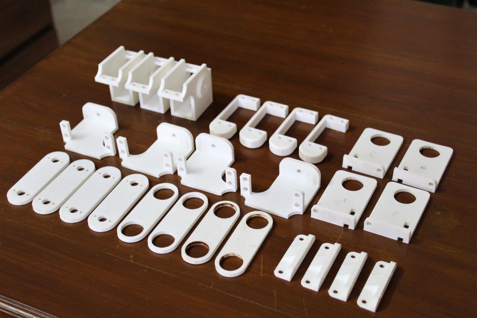
The parts required for this project had to be custom-designed therefore we used the power of digitally fabricated parts and CAD to build them. Most of the parts are 3D printed apart from a few which are laser cut out of 4mm acrylic. The prints were made at 40% infill, 2 perimeters, 0.4mm nozzle, and a layer height of 0.1mm with PLA. Some of the parts do require supports since they have a complex shape with overhangs, however, the supports are easily accessible and can be removed using some cutters. You can pick the color of your choice of the filament. Below you can find the complete list of parts and the STLs to print your own version and the 2D designs for the laser cut parts.
Note: From here on the parts will be referred to using the names in the following list.
3D printed parts:
- hip servo bracket x 2
- hip servo bracket mirror x 2
- knee servo bracket x 2
- knee servo bracket mirror x 2
- bearing holder x 2
- bearing holder mirror x 2
- leg x 4
- servo horn link x 4
- bearing link x 4
- arduino holder x 1
- distance sensor holder x 1
- L-support x 4
- bearing bush x 4
- servo horn spacer x 24
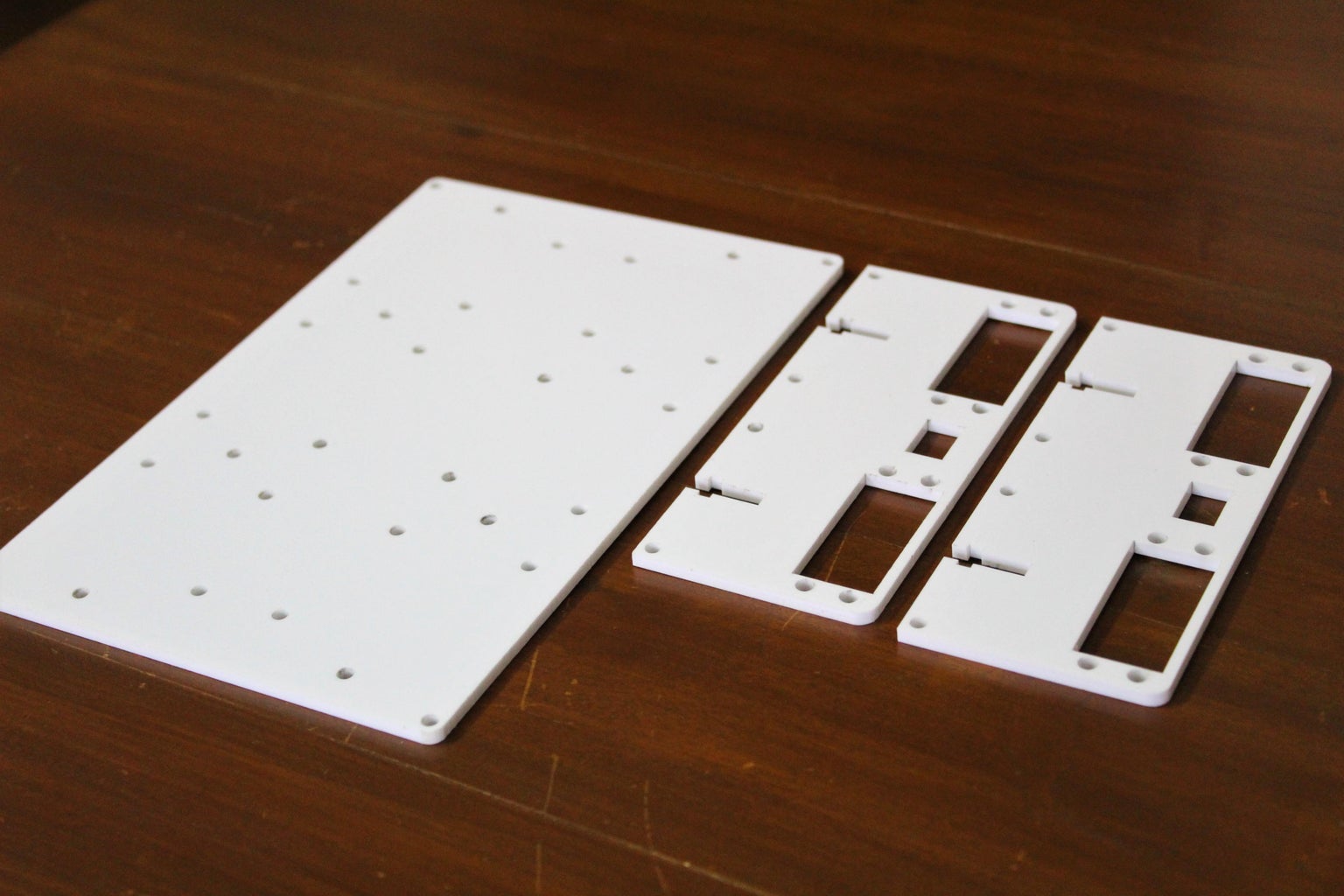
Laser-cut parts:
- servo holder panel x 2
- top panel x 1
In total, there are 30 parts that need to be 3D printed excluding the various spacers, and 33 digitally fabricated parts in total. The total printing time is about 30 hours.
Attachments


Step 4: Preparing the Links
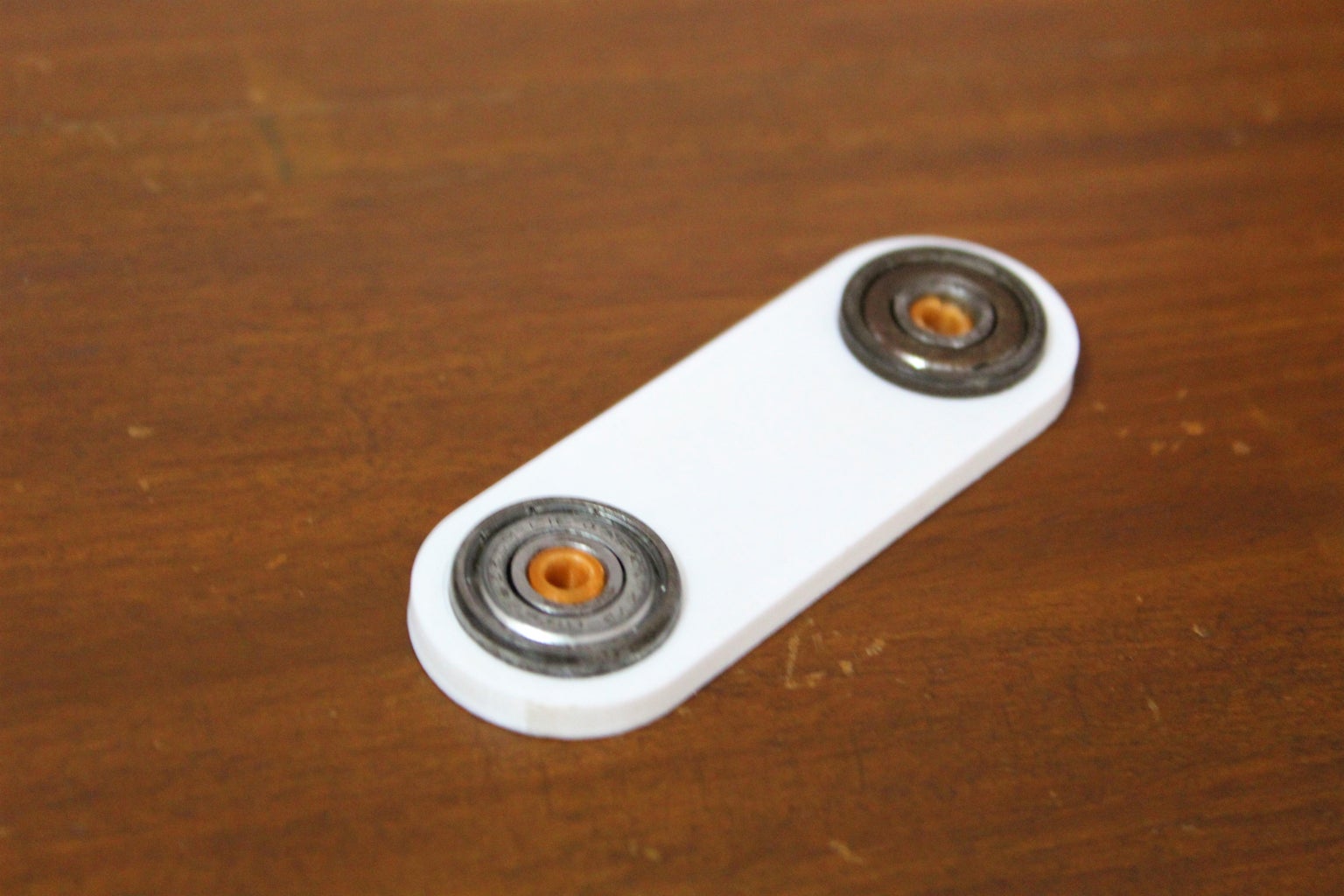


You can begin the assembly by setting up some parts at the beginning which will make the final assembly process more manageable. You can start with the link. To make the bearing link, lightly sand the inner surface of the holes for the bearing then push the bearing into the hole on both ends. Make sure to push the bearing in till one side is flush. To build the servo horn link, grab two circular servo horns and the screws that came along with them. Place the horns on the 3D print and line up the two holes, next screw the horn onto the 3D print by attaching the screw from the 3D print side. I had to use some 3D printed servo horn spacers since the screws that were supplied were a bit long and would intersect with the servo motor body while it rotated. Once the links are built you can begin to set up the various holders and brackets.
Repeat this for all 4 links of both types.
Step 5: Preparing the Servo Brackets
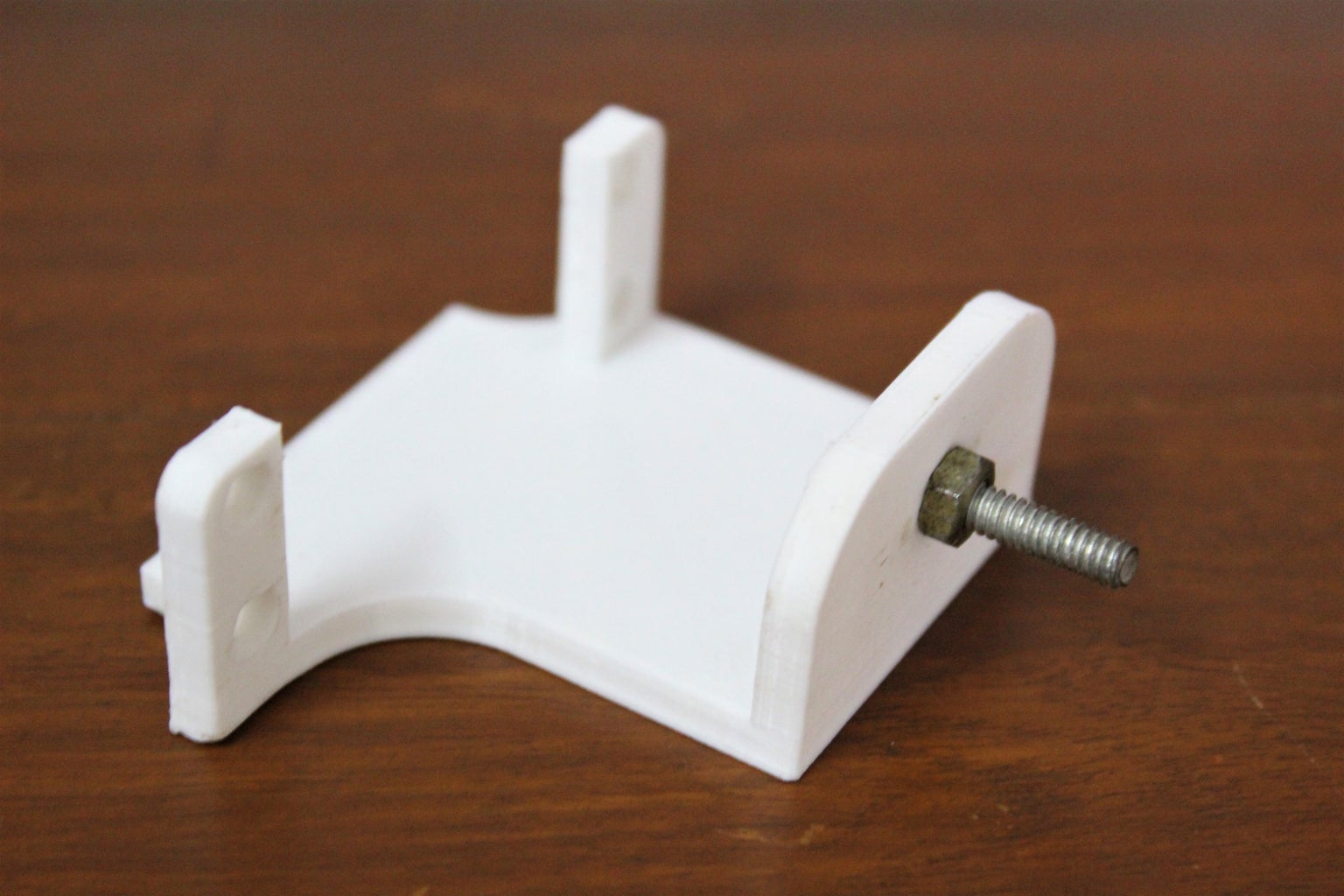


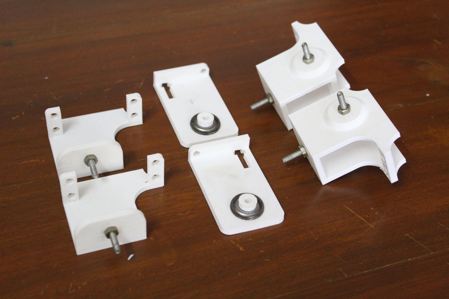
To set up the knee servo bracket, simply pass a 4mm bolt through the hole and fasten it with a nut. This will function as the secondary axle for the motor. From the hip servo bracket, pass two bolts through the two holes and fasten them with two more nuts. Next, grab another circular servo horn and attach it to the slightly elevated section of the bracket using the two screws that came with the horns. Once again I would recommend you use the servo horn spacer so that the screws do not protrude into the gap for the servo. Finally, grab the bearing holder part and push a bearing into the hole. You may need to lightly sand the inner surface for a good fit. Next, push a bearing push into the bearing towards that the bearing holder piece bends.
Refer to the pictures attached above while building the brackets. Repeat this process for the rest of the brackets. The mirrored ones are similar, only everything is mirrored.
Step 6: Assembling the Legs


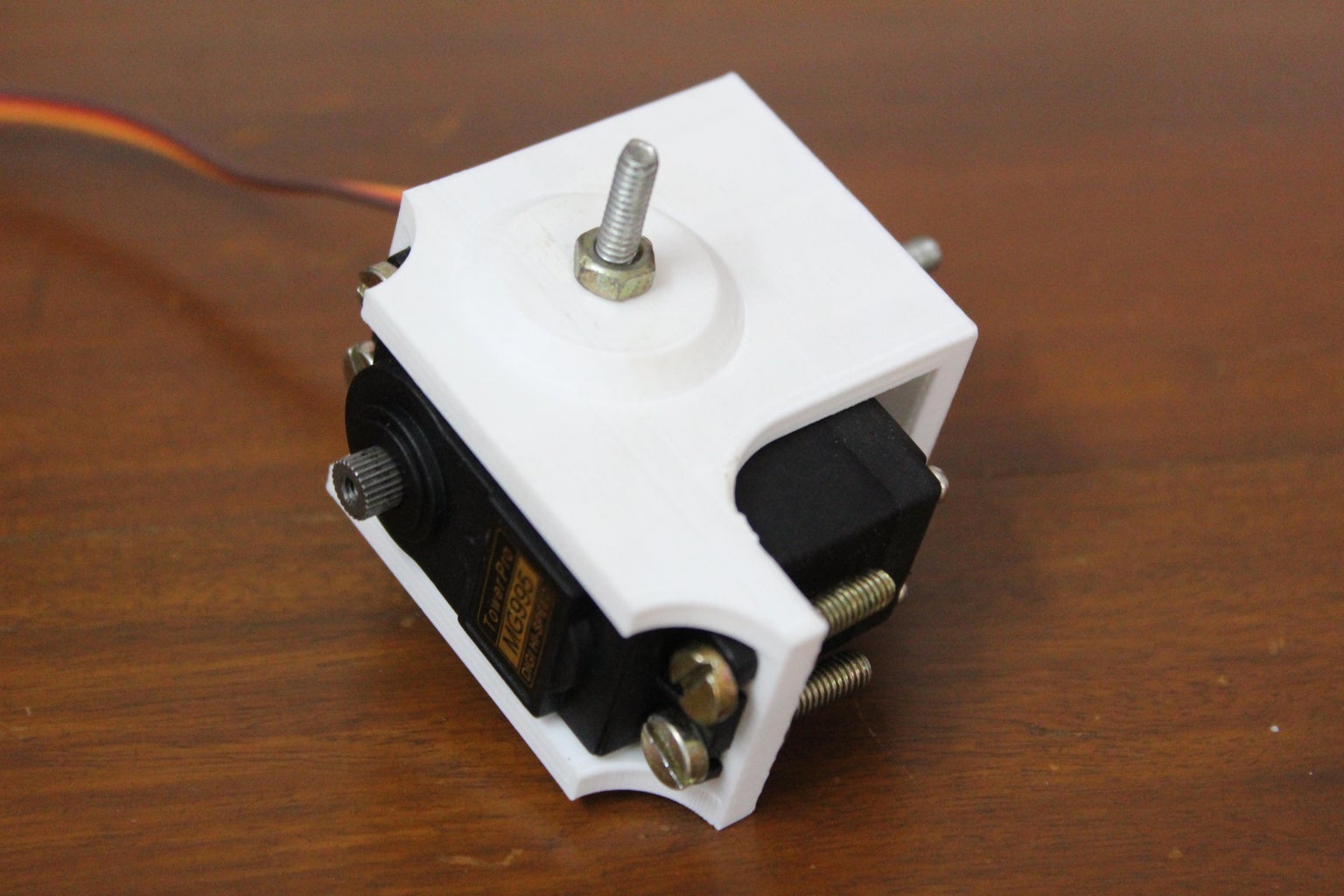
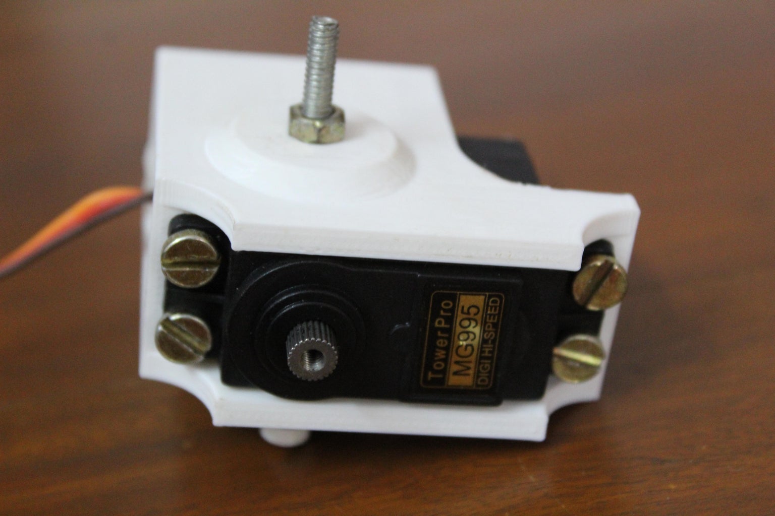
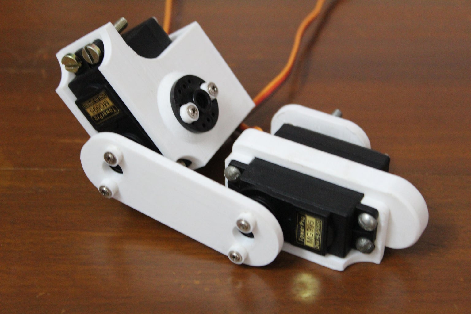

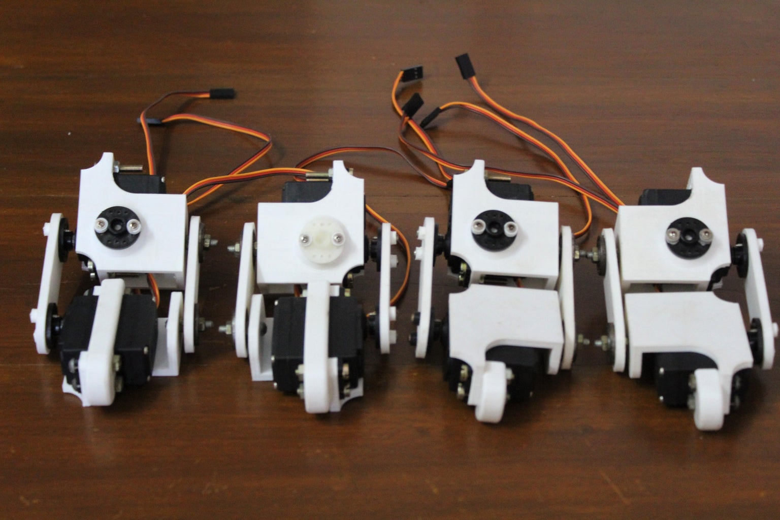
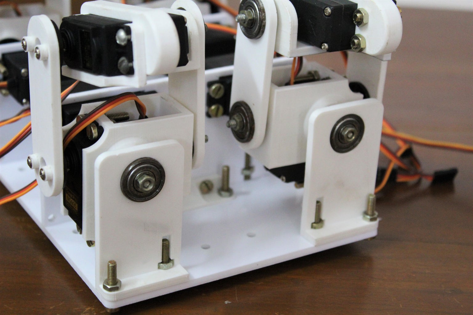
Once all of the links and brackets are assembled you can begin to build the four legs of the robot. Begin by attaching the servos onto the brackets using 4 x M4 bolts and nuts. Make sure to align the axle of the servo with the protruding bolt on the other side.
Next, link the hip servo with the knee servo using the servo horn link piece. Don't use a screw just yet to secure the horn onto the servo motor axle since we may need to adjust the position later on. On the opposite side, mount the bearing link containing the two bearings onto the protruding bolts using nuts.
Repeat this process for the rest of the three legs and the 4 legs for the quadruped are ready!
Step 7: Assembling the Body


Next, we can focus on building the body of the robot. The body houses four servo motors which give the legs their 3rd degree of freedom. Begin by using 4 x M4 bolts and buts to attach the servo onto the laser cut servo holder panel.
Note: Make sure that the servo is attached such that the axle is on the outer side of the piece as seen in the pictures attached above. Repeat this process for the rest of the three servo motors keeping in mind the orientation.
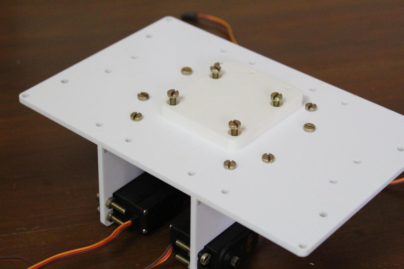
Next, attach L-supports on both sides of the panel using two M4 nuts and bolts. This piece allows us to firmly secure the servo holder panel to the top panel. Repeat this process with two more L-supports and the second servo holder panel holding the second set of servo motors.
Once the L supports are in place, use more M4 nuts and bolts to attach the servo holder panel to the top panel. Begin with the outer set of nuts and bolts (towards the front and back). The central nuts and bolts also hold down the arduino holder piece. Use four nuts and bolts to attach the arduino holder from the top onto the top panel and align the bolts so that they also go through the L support holes. Refer to the images attached above for clarifications. Finally slide four nuts into the slots on the servo holder panels and use bolts to secure the servo holder panels to the top panel.
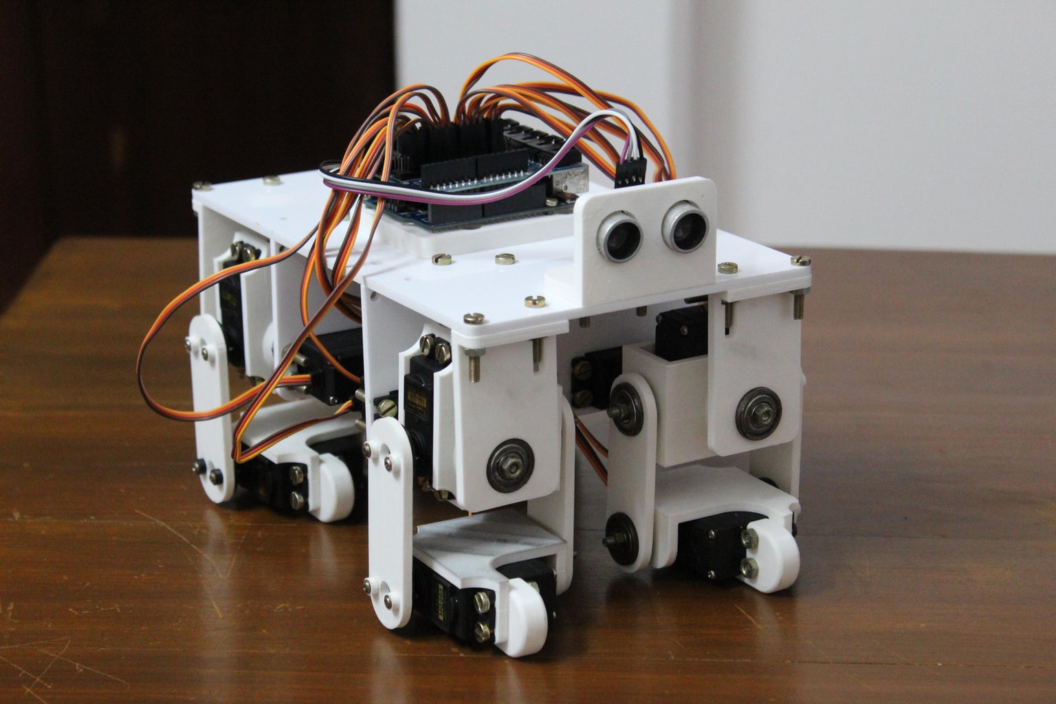
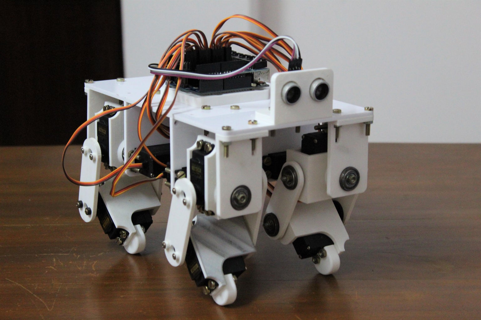
Step 8: Putting It All Together


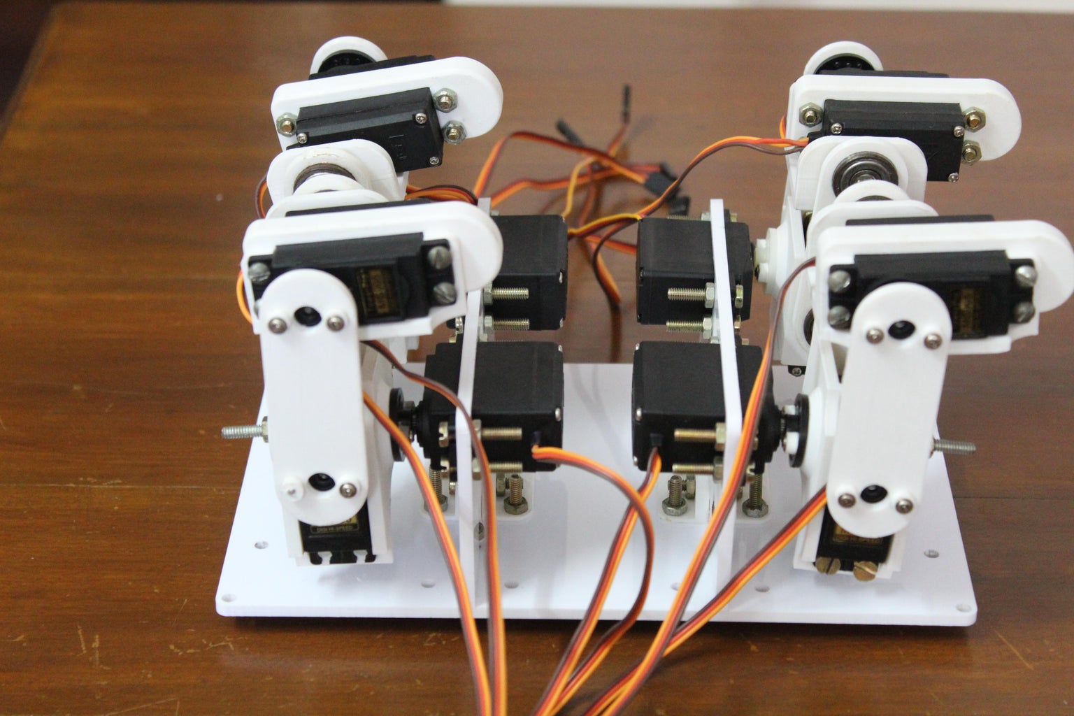


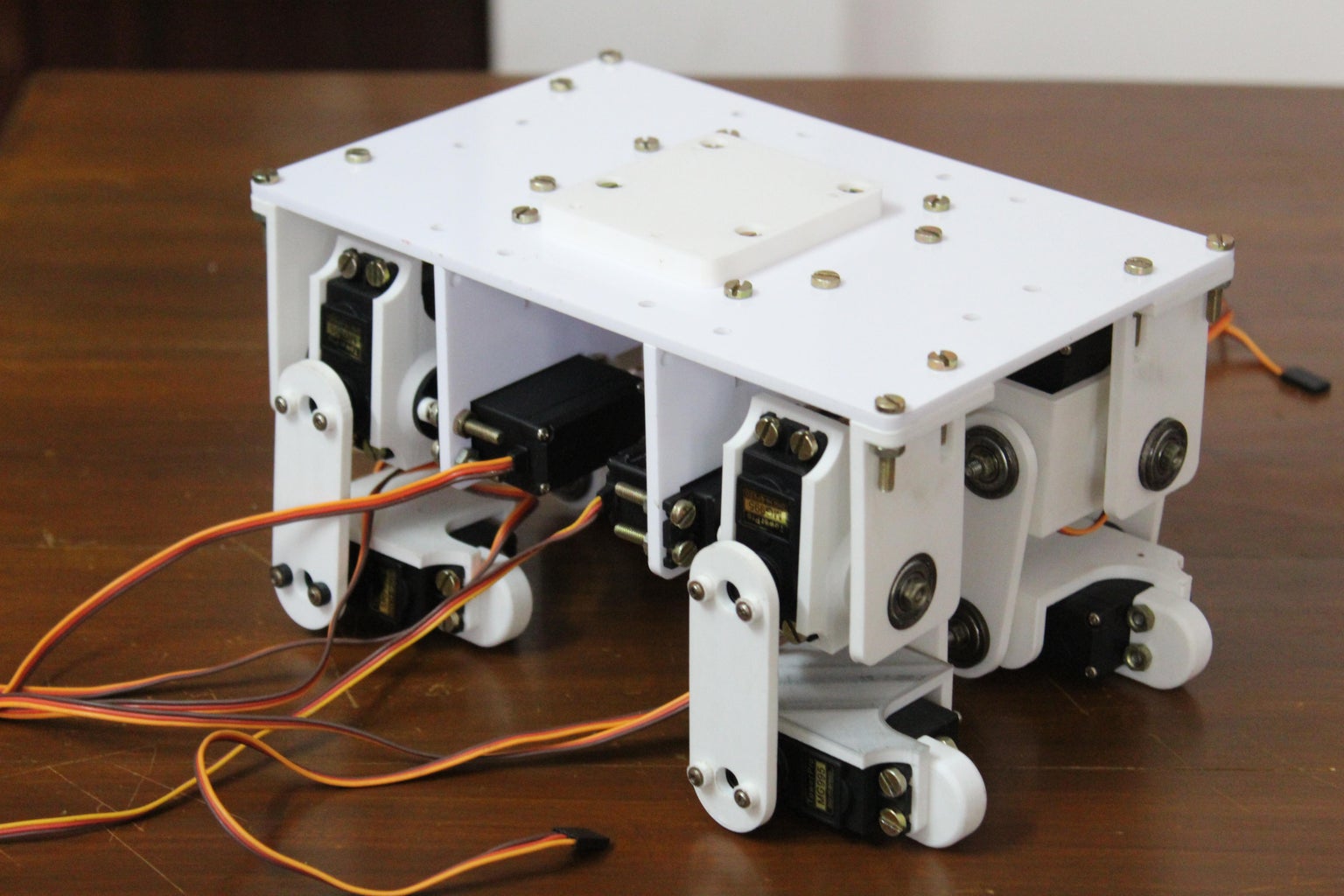
Once the legs and body are assembled you can start to complete the assembly process. Mount the four legs to the four servos using the servo horns that were attached to the hip servo bracket. Finally, use the bearing holder pieces to support the opposite axle of the hip bracket. Pass the axle through the bearing and use a bolt to secure it in place. Attach the bearing holders to the top panel using two M4 nuts and bolts.
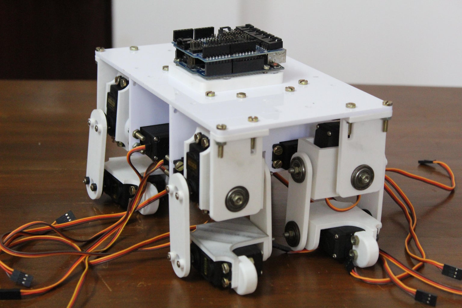
With this the hardware assembly of the quaduped is ready.
Step 9: Wiring and Circuit

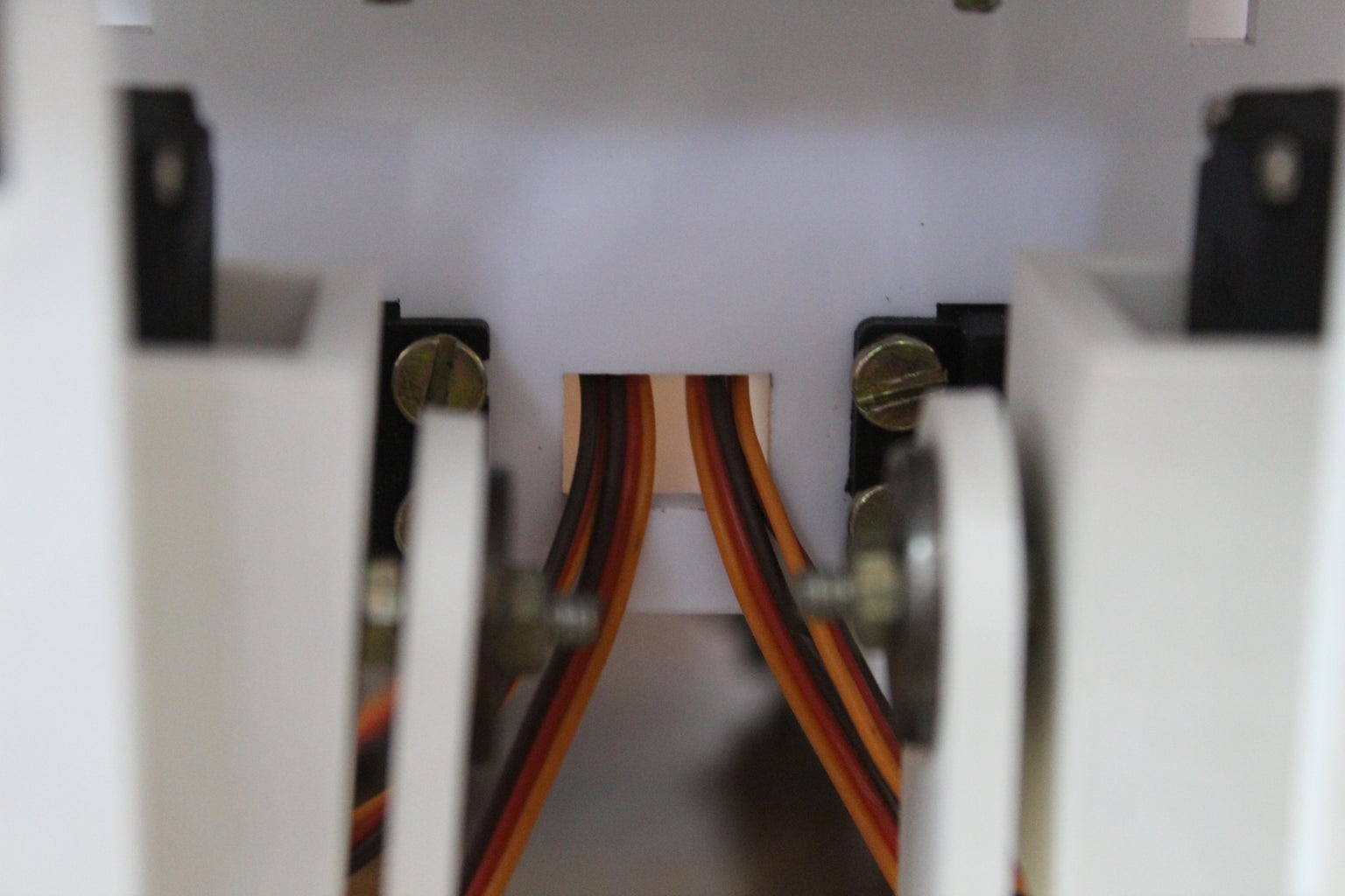
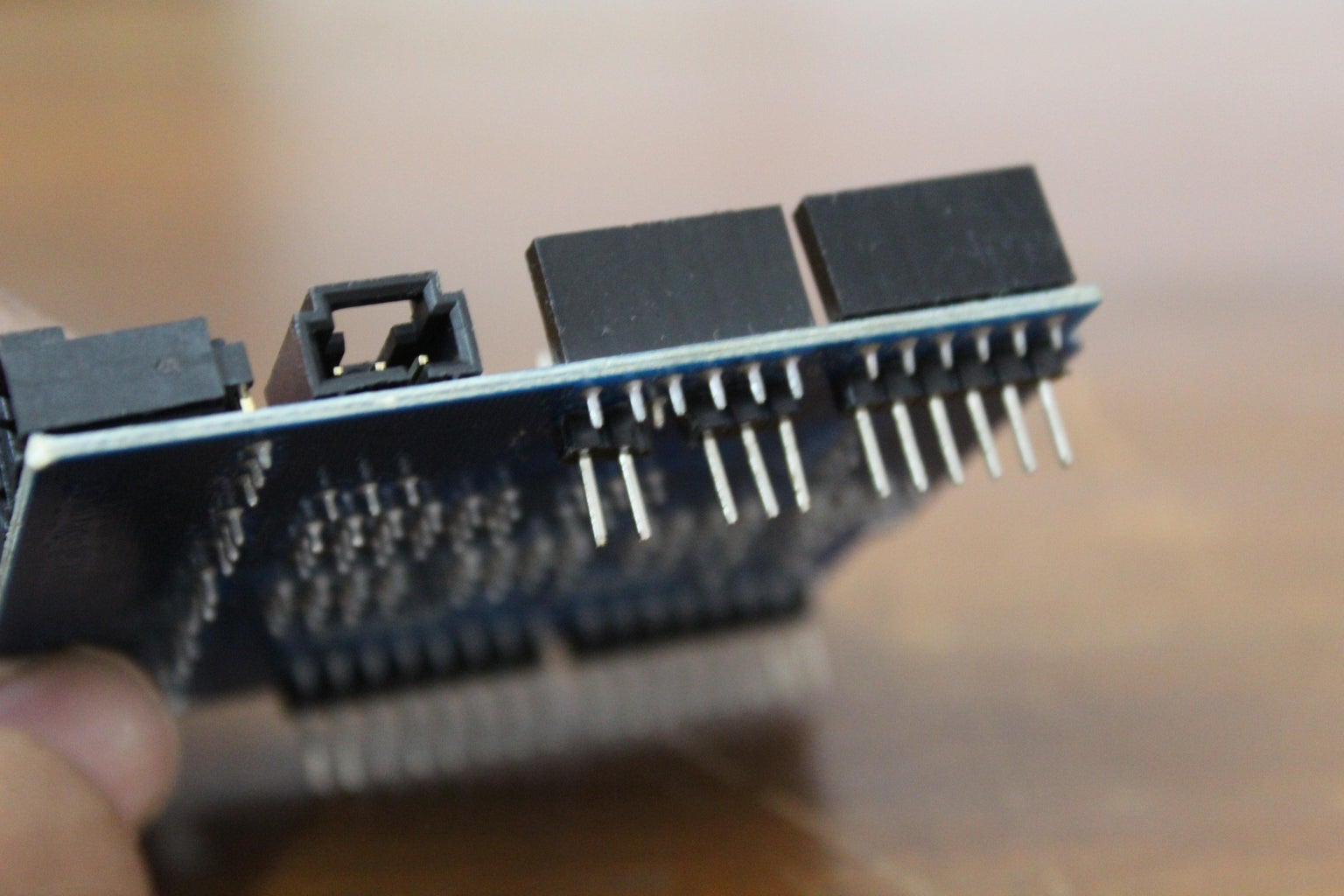

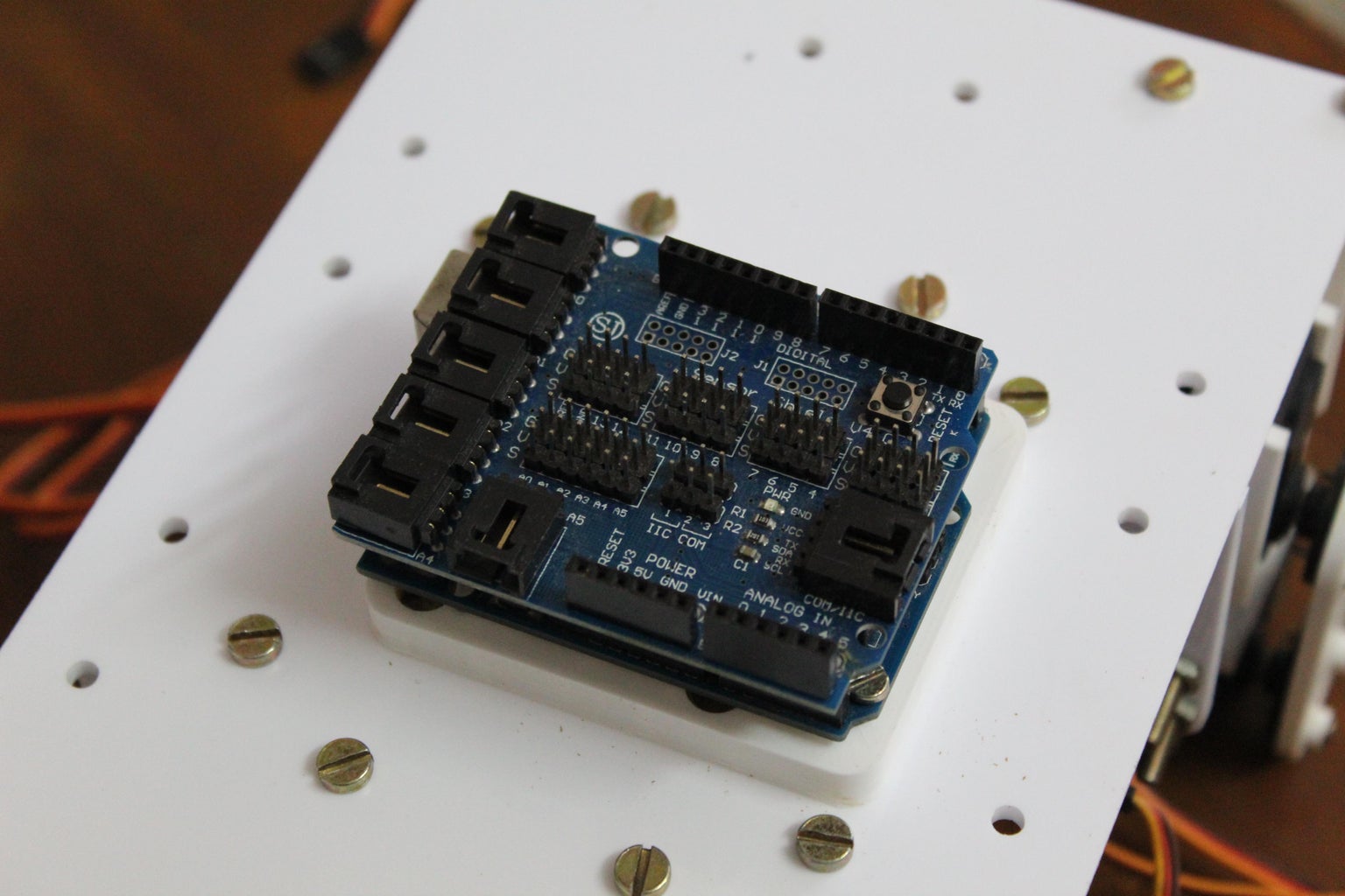


I decided to use a sensor shield that provided connections for servo motors. I would recommend that you use the sensor shield v5 since it features an onboard external power supply port. However, the one that I used did not have this option. Looking at the sensor shield more closely, I noticed that the sensor shield was drawing power from the Arduino's onboard 5v pin (which is a terrible idea when it comes to high power servo motors since you risk damaging the Arduino). The fix to this problem was to bend the 5v pin on the sensor shield out of the way so that it would not connect to the 5v pin of the Arduino. In this way, we can now provide external power through the 5v pin without damaging the Arduino.
The connections of the signal pins of the 12 servo motors are indicated in the table below.
Note: Hip1Servo refers to the servo attached to the body. Hip2Servo refers to the servo attached to the leg.
Leg 1 (forward left):
- Hip1Servo >> 2
- Hip2Servo >> 3
- KneeServo >> 4
Leg 2 (forward right):
- Hip1Servo >> 5
- Hip2Servo >> 6
- KneeServo >> 7
Leg 3 (back left):
- Hip1Servo >> 8
- Hip2Servo >> 9
- KneeServo >> 10
Leg 4 (back right):
- Hip1Servo >> 11
- Hip2Servo >> 12
- KneeServo >> 13
Step 10: Initial Setup
Before beginning to program complex gaits and other movements, we need to set up the zero points of each servo. This gives the robot a reference point which it uses to perform the various movements.
To avoid damages to the robot you can remove the servo horn links. Next, upload the code that is attached below. This code places each of the servos at 90 degrees. Once the servos have reached the 90-degree position you can reattach the links such that the legs are perfectly straight and the servo attached to the body is perpendicular to the top panel of the quadruped.
At this point, because of the design of the servo horns, some of the joints may still not be perfectly straight. The solution to this is to adjust the zeroPositions array found on the 4th line of the code. Each number represents the zero position of the corresponding servo (the order is the same as the order in which you attached the servo to the Arduino). Tweak these values a bit till the legs are perfectly straight.
Note: Here are the values that I use although these values may not work for you:
int zeroPositions[12] = {93, 102, 85, 83, 90, 85, 92, 82, 85, 90, 85, 90};
Attachments
Step 11: A Bit About the Kinematics


To make the quadruped perform useful actions such as running, walking, and other movements the servos need to be programmed in the form of motion paths. Motion paths are paths along which the end effector (the feet in this case) travel along. There are two ways of achieving this:
- One approach would be to feed the joint angles of the various motors in a brute force manner. This approach can be time-consuming, tedious, and also filled with errors since the judgment is purely visual. Instead, there is a smarter way of achieving the desired results.
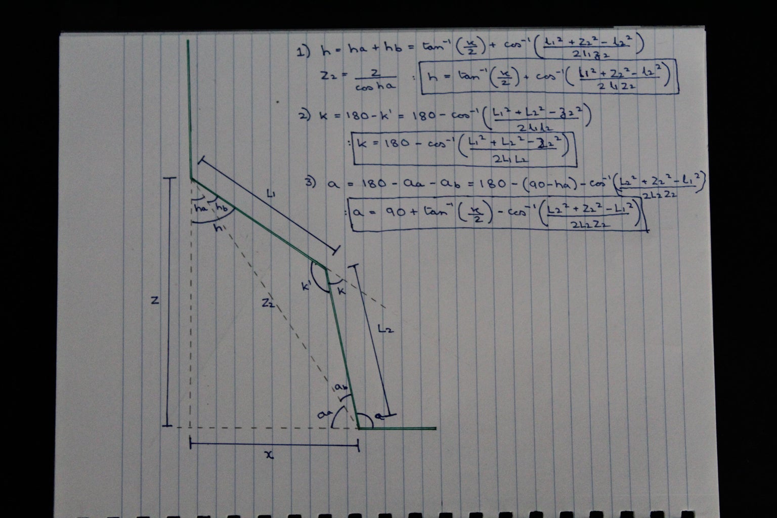
- The second approach revolves around feeding the coordinates of the end effector instead of all the joint angles. This is what is known as Inverse Kinematics. The user inputs coordinates and the joint angles adjust to position the end effector at the specified coordinates. This method can be considered as a black box that takes as inputs a coordinate and outputs the joint angles. For those who are interested in how the trigonometric equations of this black box were developed can look at the diagram above. For those who are not interested, the equations are already programmed and can be used using the pos function which takes as input x, y, z, which is the cartesian location of the end effector and outputs three angles corresponding to the motors.
The program containing these functions can be found in the next step.
Step 12: Programming the Quadruped

Once the wiring and initialization is complete, you can program the robot and generate cool motion paths so that the robot performs interesting tasks. Before you proceed, change the 4th line in the attached code to the values that you had set in the initialization step. After uploading the program, the robot should begin to walk. If you notice that some of the joints are reversed you can simply change the corresponding direction value in the direction array in line 5 (if it is 1 make it -1 and if it is -1 make it 1).
Attachments
Step 13: Final Results: Time to Experiment

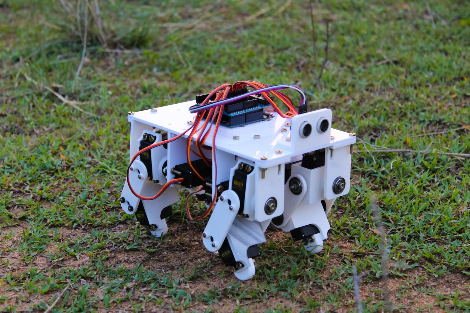


The quadruped robot can take steps that vary from 5 to 2 cms long. The speed too can be varied while keeping the gait balanced. This quadruped provides a robust platform to experiment with various other gaits and other objectives such as jumping or complete tasks. I would recommend you to try to change the motion paths of the legs to create your own gaits and discover how various gaits affects the performance of the robot. I have also left multiple mounting points at the top of the robot for additional sensor such as distance measuring sensors for obstacle avoidance tasks or IMU for dynamic gaits on uneven terrain. One could also experiment with an additional gripper arm mounted to the top of the robot since the robot is extremely stable and robust and wont tip over easily.
Hope you enjoyed this Instructable and it has inspired you to build your own.
If you liked the project do support it by dropping a vote in the "Make it Move Contest".
Happy Making!

Second Prize in the
Make it Move Contest 2020


![Tim's Mechanical Spider Leg [LU9685-20CU]](https://content.instructables.com/FFB/5R4I/LVKZ6G6R/FFB5R4ILVKZ6G6R.png?auto=webp&crop=1.2%3A1&frame=1&width=306)


