

Introduction: Arduino Segway


Hello!
More than 3 years ago I started to tinker a homemade segway. Though it's still not really finished (I have to replace the 250W Motors by 500W-models) my children are able to drive around.
If you're going to build one you will Need the following parts:
* wheelset: In my case I use 12 1/2 x 2.75 tires usually taken for dirt bikes (f.e. www.amazon.de/HMParts-REIFEN-MIT-SCHLAUCH-12/dp/B0038X9ODA; http://www.ebay.com/itm/Tire-Rear-Wheel-Mini-Pocket-Dirt-Bike-47cc-49cc-50cc-COOLSTER-QG-50-RX1-Traxxis-/182346539856?hash=item2a74b36350:g:BxUAAOSwh6xTtmwX&vxp=mtr)
* batteries: I use two 12V/12Ah lead accumulators to get 24V for the Motors
* Motors: At the moment two 24V/250W models but the 500W-motors are already waiting for their use
* for the axle I asked a local welder and some of my bicycle-parts (bar, stem) fit perfect too.
Step 1: The Motor Driver


First I tried a homemade full-bridge. To control it I used the analog-out (pwm) of the arduino. But with this variant I didn't succeed. Therefore I bought a commercial product, a 2x60A Motor Driver from sabertooth (www.dimensionengineering.com/products/sabertooth2x60).
The arduino is able to communicate with the sabertooth via a simplified serial code.


Step 2: The Angle Determination


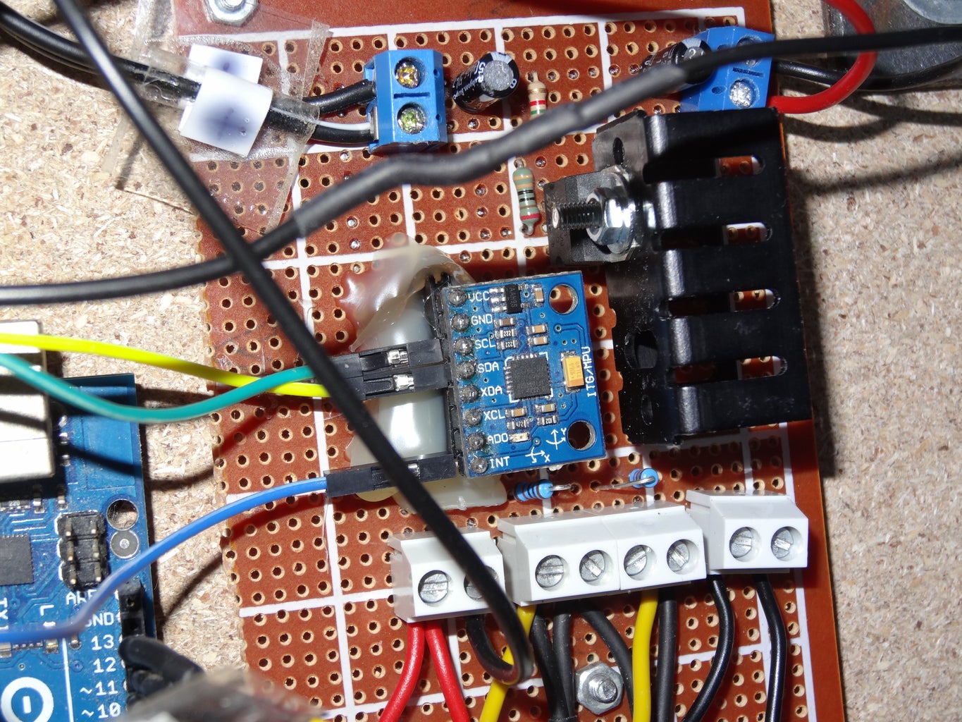
To determinate the current angle I first used a separate accelerometer (ADXL335) and gyroscope (LY530AL). Last week I changed this Setup and the two boards have been replaced by the MPU6050.sensor, which combines the two elements.
The advantage of the gyroscope is, that accelerations don't influence the measurements. The disadvantage is, that the gyro has a drift and after a while the angle goes higher and higher.
The Advantage of the accelerometer is, that it doesn't show any drift like the gyro. But it's being influenced by accelerations, which change the Output.
A filter combines both pro's so the calculated angle is near the real value. This filter can be a simple complementary-filter (like in the Picture) or the more complicated kalman-filter. The Input of the kalman-filter is the actual angle measured by the accelerometer, the angular Speed measured by the gyroscope and the time-step between two measurements. With these Parameters the kalman-filter is able to calculate an angle, which follows the gyro in times of high accelerations and in times of less accelerations it approaches the value of the accelerometer. In the Picture you can see the drift of the gyro and the good Job of the filter.
Step 3: The PID-controller


The segway tries to get the angle down to 0°. If the angle is positive, the segway brakes or accelerates backwards. If it's negative the segway accelerates forward.
But which signal get the motors? This is exactly the task of the pid-Controller.
The proportional-part: The angle should be 0°. So the greater the angle, the higher the speed of the motors.
Mathematically you can write:
angle_error = angle_should - angle_is
p-Motor-value = k_p * angle_error
The integral-part: When the current angle isn't zero, the Controller tries to get the segway horizontally again. But this approach shouldn't be slow and the smaller the angle-values, the slower the changes. Therefore the Controller allows a faster approach with the disadvantage, that the movement doesn't stop at 0° and goes a bit to the other side. This behaviour is guaranteed by the integral-part. All the angles are added (integrated) and this integral over time should be Zero. So if the angle is f.e. positive for a while, the Controller tries to get the seqway into the negative area. This guaranteeds faster approaches...
Mathematically you can write:
error_sum_new = error_sum_old + error
i-motor-value = k_i * (error_sum_new)
error_sum_old = error_sum_new
The derivative-part: Not just the current angle is important but also the changes of the angle. Let me explain: If the angle is f.e. 10° and it doesn't Change a lot, the Motors don't need to correct this shift very fast. But if the angle is 10° and it changes very fast (high derivative), than the motors have to correct this also very fast.
Mathematically you can write:
d-motor-value = k_d * angular Speed
Finally you get: motor-value = p-motor-value + i-motor-value + d-motor-value
Step 4: The Complete Setup
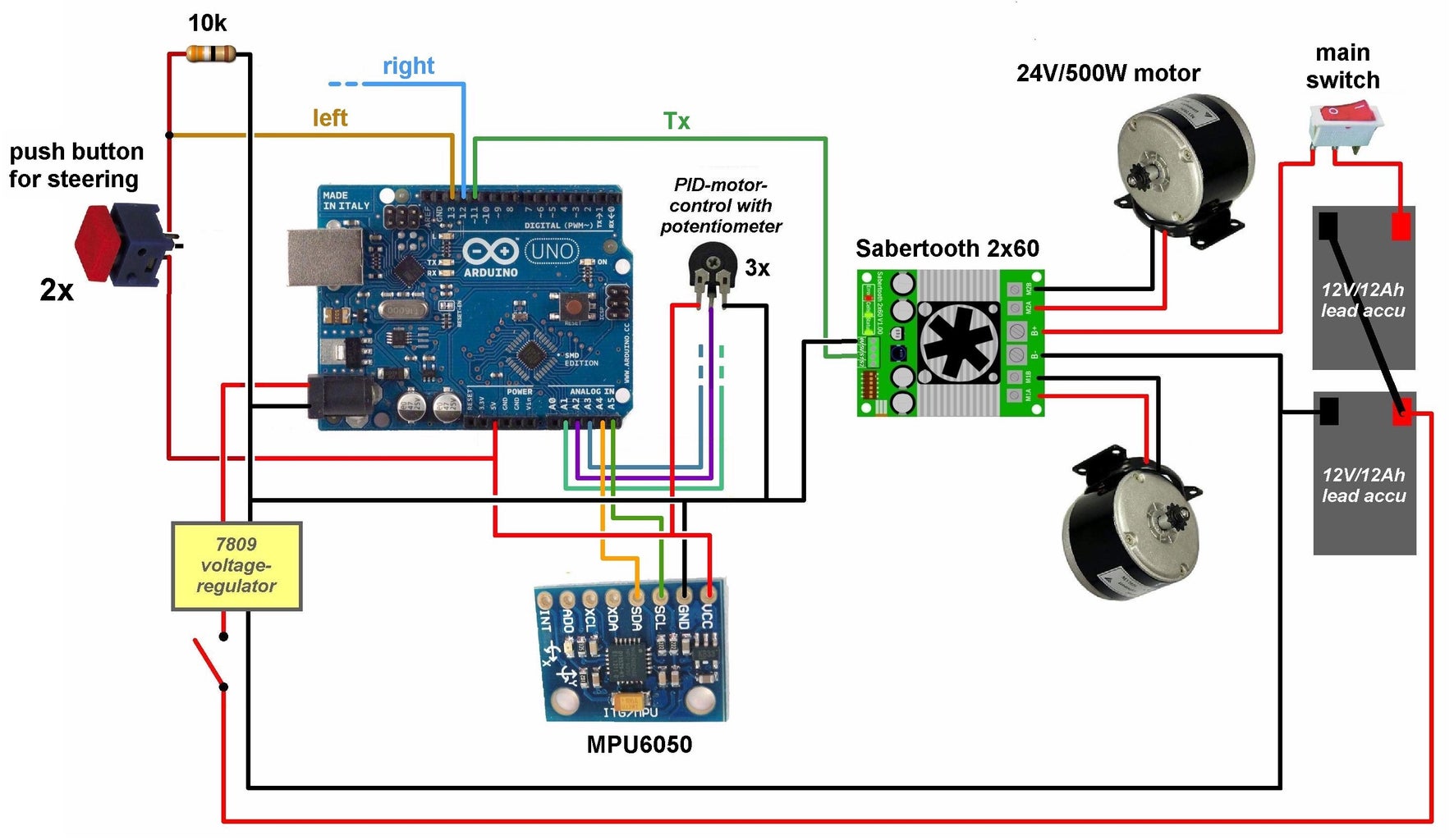


Now it's time to start the segway. To drive not only straight ahead you have to mount two buttons. When you push f.e. the right one, the left Motor increases Speed and the right Motor slows down. To ensure smooth transitions the added and deducted value starts at zero and increases step by step (+0.5 every loop) until he reaches the maximum value (f.e. 30).
To try out your own segway I 've attached the simple program for you. Good luck and don't follow the segway-inventor James Heselden down a cliff ;-)
Maybe you want to take a look at my YouTube-channel: www.youtube.com/user/stopperl16/Videos
more physics projects: https://stoppi-homemade-physics.de/

Second Prize in the
Arduino Contest 2016


