

Introduction: IO Watch (Arduino IDE Powered Wristwatch)


The iO Watch (Arduino IDE Powered Wristwatch) is now LIVE and available to preorder on tindie!
Watch uses the same microcontroller as one on Arduino UNO - super hackable and easy to use! In this instructable, I'll be showing how you can make your own programmable wristwatch - from the design process to sourcing parts, soldering and programming.
This simple digital watch is inspired by the Eiriks Binary Wrist Watch from Sverd Industries!
Stick on and let's move forward!
Step 1: Overview
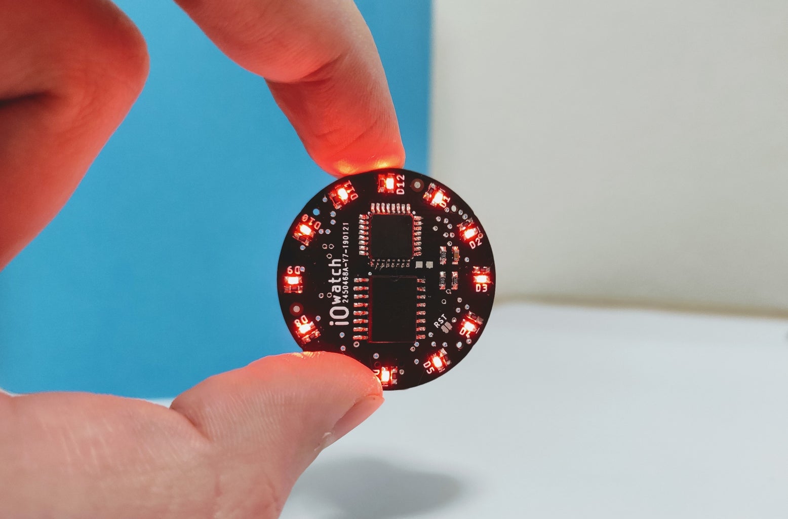


Measuring thickness at only 10 mm this wristwatch can last for a couple of years on one CR2032 battery and keep extremely precise time and even compensate for temperature using DS3231 Real Time Clock (RTC) chip with built-in crystal!
Step 2: Device Requirements

An overview of what components and tools were used in this build.
Microcontroller
The IC on this board is the ATMega328. This is the same chip that runs the Arduino Uno boards. However, this board relies on the internal oscillator of the 328, instead of having an external crystal like the Uno.
Power system
The watch has a battery holder for a 3V, 20mm coin cell battery. I recommend using the CR2032, as this has a higher capacity of 250mAh at 3V. The watch wakes up when one of two interrupt buttons are pressed. When it's time the watch enters the deep sleep mode to improve battery life.
User interface
To show the time we will use 12 LED's positioned in a circle like a simple analog watch face. for that, I picked size 0603 RED led's coupled with fairly high value (680 Ohm) resistors keeping the current low and still visible in direct sunlight. We will show the time after pressing the side button (the same one used in smartphones, because the thickens now matters).
Keeping the time
The finest RTC I can get is DS3231 keeping the time precise as it gets. Internal temperature compensation and integrated crystal make this chip ideal.
More
Full BOM can be seen HERE - most of the parts are linked on eBay or similar places so you can order it in normal quantities while LCSC and Mouser stocks are full of components in case you need more.
Step 3: PCB - Schematics and Layout


I will be using Autodesk Eagle to create a PCB. First, we will start with schematics, importing part libraries, looking trough datasheets and determining the right and logical connections. After the circuit (schematics) I designed the PCB layout and generated the Gerber and Drill files.
PCB specifications
- Layers:2
- Dimension:35mm*35mm
- Thickness:0.8
- Impedance: no
- PCB Color: Black
- Surface Finish: HASL(with lead)
- Copper Weight:1 oz
- Gold Fingers: No
- Material Details: FR4-Standard Tg 130-140C
- Panel By JLCPCB: No
- Flying Probe Test: Fully
- Test Castellated Holes: no
Then upload a Zip or RAR file containing all the gerbers and drill files to JLCPCB (cheapest) and have the PCB fabricated for 2$ + shipping cost in any color (at the time of making this instructable).

Step 4: Burning the Bootloader


If you have a brand new ATmega328 (or ATmega168/88), you'll need to burn the bootloader onto it.
The microcontroller can't interpret Arduino instructions without its initial code. It first needs a bootloader (program), which acts somewhat like the BIOS/drivers on your computer.
Bootloader has to be burned before soldering! Follow this tutorial and burn the microcontoller with following options:
- Board: ATmega328
- Bootlader: Yes
- Clock: 1 Mhz internal
- Compiler LTO: Disabled
- Variant: 328P / 328PA
- BOD: 1.8V
Once your ATmega328p has the Arduino bootloader on it, you can upload programs to it using the USB-to-serial convertor (FTDI chip) on an Arduino board.
Step 5: Soldering and Assembly


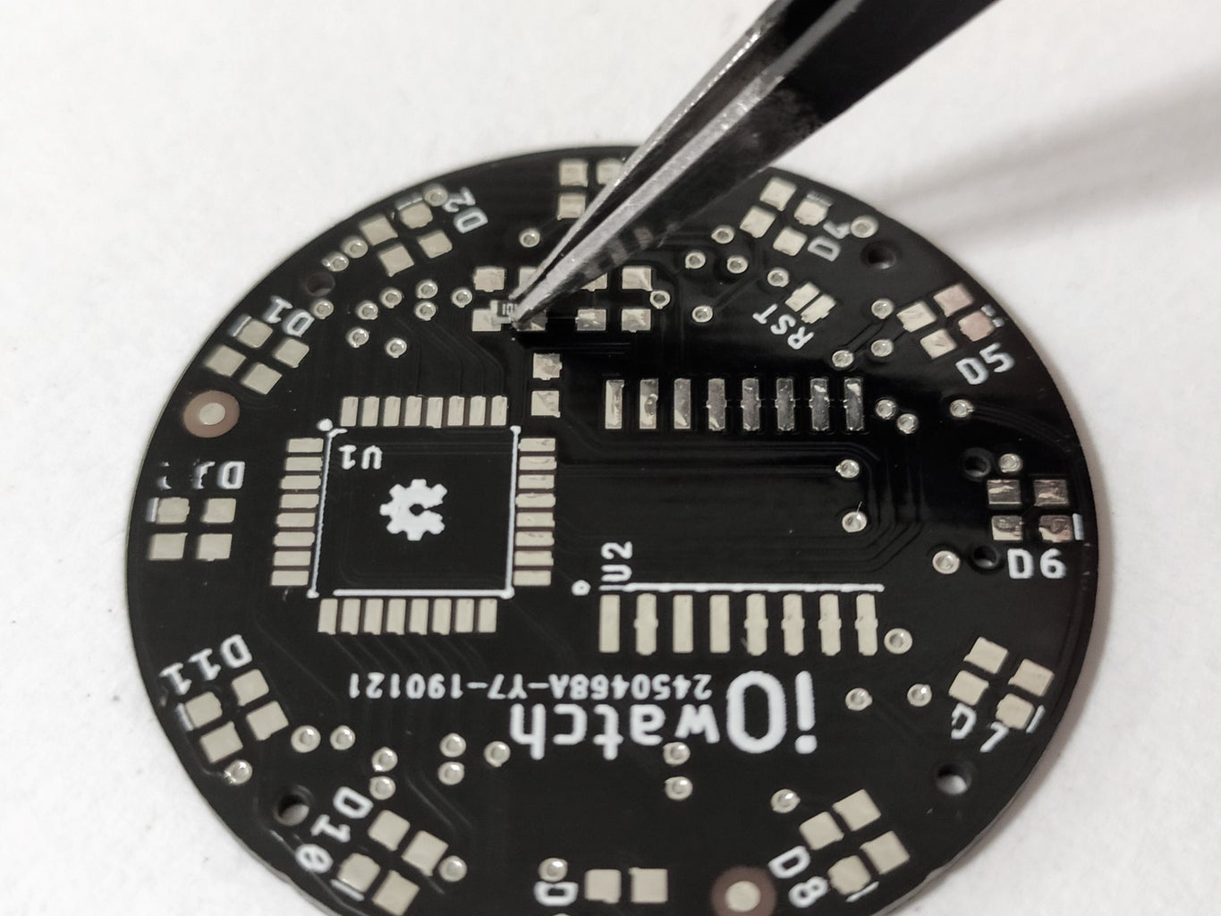

The assembly process should be fairly simple and straight forward. Gather the parts, start with one side at a time and you shouldn't run into problems.
For a detailed step by step guide visit my website.
If it's your first time soldering I definitely recommend checking some tutorials before soldering some of the smaller components 0603 etc.
Step 6: Programming


Using the FTDI test (connection) pads provided on the back of the PCB you can use a cheap FTDI converter to upload the code.
I went a step further and created a custom FTDI converter that utilizes the micro USB type B on the watch PCB so that modifying and uploading code is straight forward and easy (simply remove the battery and connect the custom converter to watch PCB and to your programming PC/MAC etc as shown in pictures).
Visit GITHUB for complete detailed instructions on how to read the time, set time and even read a temperature.
Step 7: 3D Modeling and Printing


Designed in Fusion 360, after countless versions I was finally satisfied and these are the results!
Everything except wrist watch band and glass - 3D prints, That includes
- Main body
- Outer Glass ring
- Bottom body
- Buttons
I used the following settings in Cura for my prints:
- 3D Printer - Prusa I3 MK3S
- Material: PLA
- Layer Height - 0.1 mm
- Shell Thickness - 0.8 mm (Nozzle: 0.4 - 2 Shells)
- Top and Bottom Thickness - 0.8mm
- Fill Density - 100%
- Filament - 1.75mm
- Support Type - Everywhere
- Platform adhesion Type - Skirt
Watch glass is press-fitted, so is a glass ring to the main body. PCB screws with M1.4 Phillips screws to bottom casing and then to the main casing but don't forget to place the 3D printed buttons.
In case you have trouble 3D printing, I included CAD files and adapter so that you can wear the watch as a badge!
All STL files and .f3d files can be found HERE.
Step 8: Final Notes

Thank you for reading this Instructable! Feel free to leave a comment and If you wish to know more about assembly and soldering, proceed to my web page where you can find detailed guides on how to prepare for soldering, what tools to use, step by step soldering tutorials and much more. Good luck creating your own programmable "smartwatch".
DIY KIT is now LIVE for preorder at - tindie.com
Best
Marijo


